
Optic Dynamo-Generator - Pages 41-46
PAGE 47
that kind of wiring after proving it on small scale with 26 gauge wire and 12 volt dry cell batteries, for we dare not use high voltage ourselves. We have a student who has worked with us before and is familiar with high voltage and he will come with us long enough to test our coils on house current.
We are carrying out Major Cripes suggestion to tell you what we are intending to do so you can think it over and apply it to your wiring if our tests prove out. The following describes our experiment.
1 - Instead of one wire extending from the positive and negative poles of a circuit (if you use one circuit) extend eight wires from each pole. Make two wires 14 gauge, the next two 18 gauge, and the next four 22 gauge. We can twist the tops of the wires together to simulate a cable but they must then hang free for distribution over consecutive coils, as describes by the following.
2 - We will wind the first wire around coil No. 1 clockwise, the way you would turn a right hand corkscrew with the right hand. When coil is completed it must be checked with voltmeter and rheostat for resistance.
3 - The second coil will be wound with TWO wires by adding the second wire to the first. Continue till resistance checks with coil No. 1.
4 - We will then wind No. 3 coil with the two 18 gauge wires added to the first two. We now have four wires, like four brooks joined together to give more gravity pressure to the river. Check to make it equal to the others.
5 - We will then add the four 22 gauge wires to the other four and complete coil No. 4 in same way, also checking for balance.
6 - We will then connect the eight wires of the positive pole with a large bar of iron or copper, but you will have your tank sides to solder them to.
7 - We will then repeat the operation in reverse on the other parallel series by winding them as one would wind a left hand corkscrew with the left hand. We will then connect the negative cable with the other end of the steel [iron] or copper bar. IF WE CONNECTED THE CABLES TO EACH OTHER THEY WOULD FUSE. THE BAR ITSELF WILL GRADUALLY HEAT TO RED OR WHITE HOT. You will have the tank sides to connect them to and water will be in the tank.
8 - If you use two circuits instead of one, then connect the opposite poles of each with a similar eight wire cable.
PAGE 48
This is further record of our work on The Russell's Optic dynamo and new thoughts arising from same.
Regarding checking each coil for equalizing resistance.
More mature thinking tells us that the error of doing that. These eight coils are not separate coils. They are two mates of one pair. Each four coils are one and each of the two groups of four should be checked at the number four coil for equal resistance.
We refer to Nature for reasons. Nature's every expression piles up resistance if four octave steps and focuses it maximum at the number five position between the mated pairs. THAT IS THE VERY ESSENCE OF NATURE'S POWER MULTIPLICATION PRINCIPLE.
1 2 3 4-0-4 3 2 1 HELIUM LITHIUM BERYLLIUM BORON CARBON NITROGEN OXYGEN FLUORINE 0 1 2 3 4-0-4 3 2 1
-271 186 1280 2350 3600 -210 -218 -223
The Helium octave is the central or fifth - of the nine octaves. Note that the red side of it accumulates compression rapidly until it jumps from -271 gas to plus 3600 degrees of solidity and density. The green side never reaches solidity for that octave is the turning point where genero-activity yields its maximum to radioactivity.
Take note also that resistance means compression, and compression means heat, and heat multiplication means to generate.
1 2 3 4-0-4 3 2 1 NEON SODIUM MAGNESIUM ALUMINUM SILICON PHOSPHORUS SULPHUR CHLORINE 0 1 2 3 4-0-4 3 2 1
-253 98 651 659 1470 725 119 -102
red-violet orange green green- indigo
Blue-violet red orange yellow - yellow blue blue
COLD > Heat Multiples > <-- Heat Multiples <-- COLD
Conclusion. It therefore follows that each mate pair should be considered as equal WHOLES and not as separate coils.
EXAMPLE NO.2 GROWTH OF MAN
Man starts at zero as a baby. He passes through four generative stages of multiplying power - childhood - boyhood - youth and matured manhood. Man represents the red side of the spectrum.
PAGE 49
Woman is the mate to man. She passes through the same stages of accumulating power in the same way. Woman represents the green side of the spectrum.
RIVERS AND OCEANS - EXAMPLE NOW 3.
All the brooks and rivers multiply their power and give it to all the oceans. The oceans forever divide their power and give it back to the brooks and rivers.
The very essence of Nature's power multiplication principle is to generate heat and power by compressive resistance in FOUR OCTAVE STEPS. Beyond that Nature does not allow further multiplication. NATURE'S PAIRS OF FOUR THEN MEET AND THE CYCLE REVERSES.
If we call that meeting point No. 5 the ocean, or the matured man and woman are the No. 5. The sun in our heavens represents that No. 5 position. The fulcrum of the lever also represents that No. 5 position. [see 4plusplus]
Some day we would like to explain to you what that characteristic of Nature really is, and why it is so basic. If that wave characteristic was known by present day science its mathematics would be more reliable and its axioms would be truths instead of assumptions which prove to be not truths.
REGARDING CONNECTING THE CABLE ENDS.
In our last letter we drew a diagram showing the No. 4 cable ends connected by a bar of steel or copper. You will note that the bar is not on the core axis. That was done purposely to create a minimum of heat. If the bar - especially of magnetic soft iron is placed on center - in the armature position, that would be the point of optical focus - or gravity center, where heat would be maximum.
EXAMPLES.
A bi-convex lens like Fig. 1 seen edgewise, would look like this. The arrows show the direction of increasing resistance.
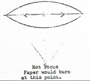
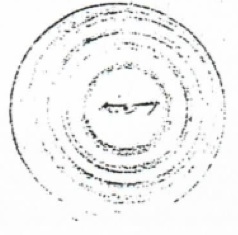
The same lens shown face view would look like this. Its hottest part (resistance) would be its outer rim. Warm rim - cool center.
PAGE 50
When we impersonate a lens with a solenoid the same effect takes place but in a less efficient manner because of the impossibility to make wires do what lenses do. Fig. 3 is a solenoid coil with a lens superimposed on it to illustrate how heat resistance always multiplies FIRST by expansion toward the rim of the lens or solenoid, then SECOND, by compression towers a focal point. [it appears there is a mis-numbering in the original document]
This it always does in four octave steps and ends in what is known as the opposite poles of a bar magnet.
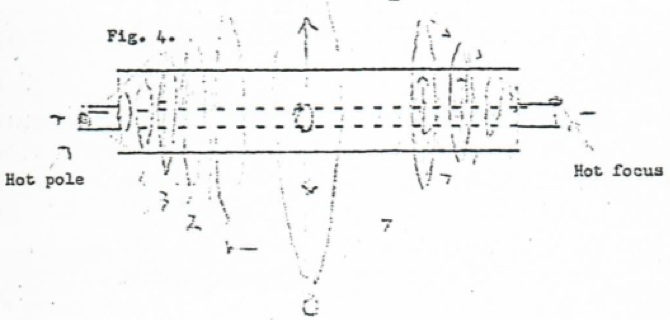
The above diagram is made to show why very little of the resistant heat will accumulate in the wires themselves. It is the diffraction rings in lenses and the turns of a coil what cause focal centers - or GRAVITY POLES - to form on the wave axis.
NOTE the wave axis is a continually extending fulcrum. Every turn in a coil is a wave lever. The fulcrum of a wave begins at its zero cathode and ends at its anode. The wave axis is always static - for the fulcrum never moves - and the lens rings and coil turns are always dynamic, for motion is continuous in its extensions.
All of this is necessary to comprehend for one who desires to know the secret of how matter emerges from space.
We will continue our work in the laboratory on Friday. We are not working Thursday for Dr. Page is coming.
With our best wishes we are Sincerely yours, Walter and Lao Russell.
PAGE 51
See Also