
On the Pitch of Musical Sounds
In order to fully describe a Musical Sound, it is necessary, besides specifying its duration, to particularize three things about it, viz., its Pitch, its Intensity, and its Quality. By pitch is meant its height or depth in the musical scale, by intensity its degree of loudness, and by its Quality, that character which distinguishes it from another sound of the same pitch and intensity.
In the present chapter we have only to do with Pitch. Inasmuch as we have seen that the Sensation of Sound is due to the vibratory motion of some body, the first question that arises is,: What change takes place in the vibratory movement, when the pitch of the sound changes?
If we stretch a violin string loosely, and pluck it, we get a low sound; stretch it more tightly, and again pluck it, a higher sound is obtained, and at the same time, we can see that it is vibrating more rapidly. Again, take in the same way a short and a long tong of metal, and the former will be found to give a higher sound and to vibrate more quickly than the latter.
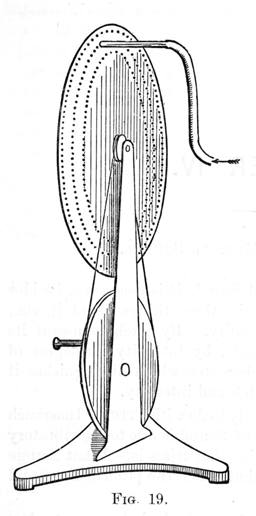
But the instrument that best shows the fact, that the more rapid the rate of vibration, the higher is the pitch of the sound produced, is perhaps the Wheel Syren (fig. 19). This consists of a disc of zinc or other metal, about 18 inches or more in diameter, mounted on a horizontal axis, and capable of being rapidly revolved by means of a multiplying wheel. The disc is perforated by a number of holes arranged in concentric circles, all the holes in each circle being the same distance apart. In order to work the instrument, a current of air is blown through an India-rubber tube and jet, against one of the circle of holes while the disc is slowly revolving. Whenever a perforation comes in front of the jet, a puff of air passes through, causing a condensation on the other side. The current of air is immediately cut off by the revolution of the disc, and consequently a rarefaction follows the previous condensation - in short, a complete sound wave is formed. Another hole appears opposite the jet, and another wave follows the first, and so on, one wave for each hole. While the disc is being slowly revolved, the waves do not follow one another quickly enough to give rise to a musical sound - each puff is heard separately; but on gradually increasing the speed, they succeed each other more and more quickly, till at last a low musical sound is heard. If we now still further increase the speed, the pitch of the sound will gradually rise in proportion.
Felix Savart's toothed wheel (fig. 4, chap. 1) is another instrument which proves the same fact. While the wheel is being slowly turned, each tap on the card is heard separately, but on increasing the speed, we get a musical sound, which rises in pitch as the rate of revolution increases, that is, as the rate of vibration of the card increases.
We see, therefore, that the pitch of a sound depends upon the vibration rate of the body, which gives rise to it. By the vibration rate, is meant the number of complete vibrations - journeys to and fro - which it makes in a given time. In expressing the vibration rate, it is most convenient to take a second as the unit of time. The pitch of any sound may therefore be defined, by stating the number of vibrations per second required to produce it; and to avoid circumlocution, this number may be termed the "vibration number" of that sound. We shall now proceed to describe the principal methods which have been devised for ascertaining the vibration number of any given sound.
One of the earliest instruments constructed for this purpose was Felix Savart's toothed wheel (fig. 4) which has just been referred to. A registering apparatus, H, which can be instantly connected or disconnected with the toothed wheel by touching a spring, records the number of revolutions made by it. In order to discover the vibration number of any given sound, the velocity of the wheel must be gradually increased until the sound it produces is in unison with the given sound. The registering apparatus is now thrown into action, while the same speed of rotation is maintained for a certain time, say a minute. The number of revolutions the wheel makes during this time, multiplied by the number of teeth on the wheel, gives the number of vibrations performed in one minute. This number divided by 60 gives the number of vibrations per second required to produce the given sound, that is, its vibration number.
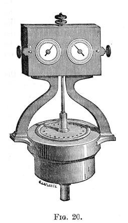
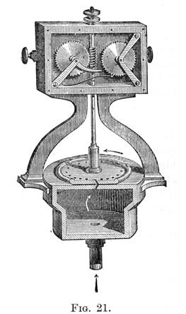
Caginard de Latour's Syren is an instrument constructed on the same principle as the Wheel Syren, but different in detail. Two brass discs, rather more than an inch in diameter, are each similarly pierced with the same number of holes arranged in a circle (figs. 20 & 21). The upper disc revolves with the least possible amount of friction on the lower one, which is stationary, and forms the upper side of a wind chest. When air is forced into the chest by means of the tube below, and the disc is made to revolve, a puff will pass through each hole, every time the holes coincide. Thus, supposing there are 15 holes, they will coincide 15 times for every revolution, and therefore one revolution will give rise to 15 sound waves. By an ingenious device, which, however, in the long run is a disadvantage, the current of air itself moves the upper disc. This is brought about by boring the holes in the upper disc in a slanting direction, while those in the lower one are bored in the opposite direction, as shown in fig. 21. On the upper part of the axis of the revolving disc, a screw is cut, in the threads of which work the teeth of the wheel shown on the left in fig. 21. Further, the right hand wheel in fig. 21 is so connected with the left hand one, that while the latter makes one revolution the former moves only one tooth. Each of these wheel has 100 teeth. On the front of the instrument (fig. 20) are two dials, each divided into 100 parts corresponding to the 100 teeth on each of the wheels, the axles of which passing through the centre of the dials, carry the hands seen in the figure. Thus the right hand dial records the number of single revolutions up to 100, and the left hand one the number of hundreds. Finally, this registering apparatus can be instantly thrown in and out of gear, by pushing the nuts seen on both sides.
Suppose now we wish to obtain, by means of this instrument, the vibration number of a certain sound on a harmonium or organ, We first see that the registering apparatus is out of gear, and then placing the syren in connection with an acoustical bellows, gradually blow air into the instrument. This causes the disc to revolve, and at the same time a sound, at first low, but gradually rising in pitch, is heard. As we continue to increase the wind pressure, the pitch gradually rises until at last it is in unison with the sound we are testing. Having now got the two into exact unison, we throw the registering apparatus into gear, and maintain the same rate of rotation, that is keep the two sounds at the same pitch for a measured interval of time - say one minute. At the expiration of this time the recording apparatus is thrown out of gear again. We now read off the number of revolutions: suppose the dial on the left stands at 21, and that on the right 36, then we know the disc has made 2,136 revolutions. Multiply this by 15 (for we have seen that each revolution gives rise to 15 waves), and we get 32,040 as the number of waves given off in one minute. Divide this by 60, and the quotient, 534, is the vibration number of the given sound.
Although this instrument does very well for purposes of lecture illustration, it has several practical defects. When, for instance, the registering apparatus is thrown into gear, the increased work which the wind has to perform in turning the cogwheels, slackens the speed, and consequently lowers the pitch. Then, again, it is very difficult to keep the blast at a constant pressure - that is, to keep the sound steady. Further, there is an opening for error in noting the exact time of opening and closing the recording apparatus. From these causes, this form of Syren cannot be depended upon, according to Mr. Ellis, within ten vibrations per second.
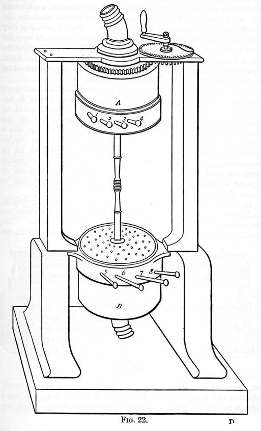
Helmholtz has devised a form of Syren, in which these sources of error are avoided. It consists really of two Syrens, A and B, fig. 22, facing one another, the discs of which are both mounted on the same axis, and driven with uniform velocity, not by the pressure of the wind, but by an electro-motor. Each disc has 4 circles of equidistant holes, the number of holes in the circles being, in the lower disc, 8, 10, 12, 18, and in the upper 9, 12, 15, 16, respectively. By means of the handles 1, 2, 3, &c., projecting from the wind chests, any or all of these circles may be closed or opened, so that two or any number of sounds up to eight, may be heard simultaneously.
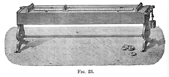
Knowing the length of a stretched string, the stretching weight, and the weight of the string itself, it is possible to ascertain the vibration number of the sound it gives by calculation. The instrument used in applying this method, is termed a Sonometer or Monochord. It consists (fig. 23) of a sound box of wood, about 5 feet long, 7 inches broad, and 5 inches deep. A steel wire is fastened to a peg at one end, passes over bridges as shown in the figure, and is stretched by a weight at the other. The sound is evolved by drawing a violin bow over the wire. In order to find the vibrational number of any given sound, the wire is first tuned in unison with it, by varying the length of the wire (by means of the movable bridge shown in fig. 23) or the stretching weight. This weight is then noted, and the vibrating part of the wire measured and weighed. If the number of grains in the stretching weight (including the weight of the adjacent non-vibrating part of the wire) be denoted by W; the number of inches in the vibrating wire by L; and the number of grains in the same by w; then the vibrational number is
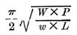
P being the length of the seconds pendulum at the place of observation, (= 39.14 at Greenwich) and pi the constant 3.14159. Although theoretically perfect, the practical difficulties of determining the unison, measuring the length, ascertaining the weights, obtaining perfect uniformity in the wire, keeping the temperature constant, together with those arising from the thickness of the wire, are so great, as to render this method of no avail where accuracy is required.
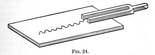
A far more accurate method of counting vibrations is that known as the Graphic method, which is, however, only applicable in general to tuning-forks. The principle of this method will be readily understood on reference to fig. 24. A light style is attached to one of the prongs of a tuning fork. A piece of paper or glass, which has been coated with lamp-black by holding it in the smoke of burning camphor or turpentine, is placed below the tuning fork so that the style just touches it. If now, while the glass remains at rest, the fork be set in vibration, the style will trace a straight line on the glass or paper, by removing the lamp black in its path as it moves to and fro. But if the glass be moved rapidly and steadily in the direction of the fork's length, a complete record of the motion of the fork will be left on the lamp-blacked surface in the form of a wavy line, each double sinuosity in which will correspond to a complete vibration of the fork. A more convenient arrangement is to fasten the lamp-blacked paper round a rotating cylinder, which is also made to travel slowly from right to left by means of a screw on the axis, so as to prevent the tracing from overlapping itself. If this cylinder be kept rotating for a certain number of seconds, the number of sinuosities traced in that time can be counted; we have then only to divide this number by the number of seconds, to obtain the vibration number of the fork.
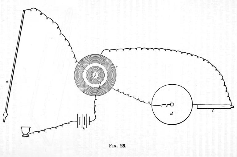
This method has been brought to a very high degree of perfection by Professor Mayer, of New Jersey. He uses lamp-blacked paper wrapped round a rotating metalic cylinder or drum, as above described. The wave curve is traced on this by an aluminium style, attached to the end of one of the prongs of the tuning fork under examination. A pendulum (a, fig. 25), beating seconds, has a platinum wedge fastened to it below, which, at every swing, makes contact with a small basin containing mercury. This basin is in communication with one pole of a battery (b ), a wire from the other pole being attached to the primary coil (p ) of an inductorium, from which again a wire proceeds to the top of the pendulum. The wire from one end of the secondary coil (s) is attached to the stem of the tuning fork (t), and that from the other end to the revolving cylinder (d). When the apparatus is at work, it is obvious that a spark will pierce the smoked paper at every contact of the pendulum with the mercury, leaving a minute perforation. The number of complete sinuosities between two consecutive perforations, will consequently be the vibration number of the fork.
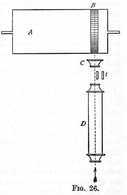
A new instrument for counting rapid vibrations, called by its inventors, the Cycloscope, was devised a few years ago by McLeod and Clarke. A diagrammatic representation of the essential parts of the apparatus is shown in fig. 26. A is a drum, rotating on a horizontal axis, and capable of being revolved at any definite rate. Round this is fastened a strip of dark paper B, ruled with equidistant white lines. C is a 2" objective, giving an image of the white lines, which is viewed through the microscope, D. The tuning fork (t) to be tested is fastened vertically in a vice, so that one of the prongs is situated in the common focus in such a way as to obscure about one-fourth of the field of view. Thus, on looking through the microscope when everything is at rest, an image of the white lines is seen, and the part of the prong (a, fig. 27A), of the tuning fork partially obscuring them; (b) is a scale fixed in the eye-piece. When the fork is set vibrating and the drum is rapidly rotated, the lines can no longer be separately distinguished; but, just as, in the Graphic method, we found a wave to result from two movements at right angles, so by the composition of the fork's motion with that of the white lines, a wave makes its appearance, (fig. 27, ![]() .
.
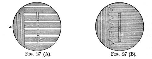
If the white lines pass through a space equal to the distance between two of them, while the fork makes one vibration, then the length of the wave will be the distance between two white lines as seen through the microscope; furthermore, if this is the case exactly, the wave will appear stationary. If, however, the drum rotates faster or slower than this, the wave will have a slow apparent motion, either upwards or downwards. As the velocity of rotation of the drum is under the control of the observer, it is easy to keep it at such a speed, that the wave appears stationary, that is, at such a speed that white lines pass through a space equal to the distance between two of them while the fork makes one vibration. It follows, therefore, that the number of white lines that pass over the field of view during the time of the experiment, is equal to the number of vibrations executed by the fork in that time. An electric pendulum, beating seconds, gives the time, while an electric counter records the number of revolutions made by the drum. A fine pointed tube, filled with magenta, automatically marks the paper on the drum at the beginning and end of the experiment, so as to give the fractional part of a revolution. The number of white lines that pass the field of view is thus easily obtained, by multiplying the number of white lines round the drum by the number of revolutions and fractional part of a revolution made by it. This, divided by the number of seconds the experiment lasted, gives the vibration number of the fork. In the hands of the inventors, this instrument has given extremely accurate results.
Another very accurate counting instrument is the Tonometer, an account of which is deferred, until the principle on which it is constructed have been explained (see Chap. xiii).
The exactness with which pitch can now be determined, is shown by the following abridged table, taken from Mr. Ellis's "History of Musical Pitch," p. 402. In the first column are the names of five particular forks, the vibrational numbers of which are given in the second, third, and fourth columns, as determined independently by McLeod with the Cycloscope, Ellis with the Tonometer, and Mayer with his modification of the Graphic method, respectively.
| Name of fork | McLeod | Ellis | Mayer |
| Conservatoire | 439.55 | 439.54 | 439.51 |
| Tuileries | 434.33 | 434.25 | 434.33 |
| Feydeau | 423.02 | 423.01 | 422.98 |
| Versailles | 395.83 | 395.79 | 395.78 |
| Marloye | 255.98 | 255.96 | 256.02 |
Knowing the velocity of sound in air, and having ascertained the vibrational rate of any sounding body by one of the preceding methods, it is easy to deduce the length of the sound waves emitted by it. For, taking the velocity of sound as 1,100 feet per second, suppose a tuning fork, thevibration number of which is say 100, to vibrate for exactly one second. During this time it will have given rise to exactly 100 waves, the first of which at the end of the second will be 1,100 feet distant from the fork; the second one will be immediately behind the first, and the third behind the second, and so on: the last one emitted being close to the fork. Thus the combined lengths of the 100 waves will evidently be 1,100 feet, and as they are all equal in length, the length of one wave will be
1100 - - - - = 11 ft. 100
To find the wavelength of any sound, therefore, it is only necessary to divide the velocity of sound by the vibration number of the sound in question. It will be noticed that as the velocity of sound varies with the temperature of the air, so the wavelength of any particular sound must vary with the temperature.
We have seen that the pitch of any sound depends ultimately upon the rapidity with which the sound waves strike the tympanum of the ear, and usually this corresponds with the rate of vibration of the sounding body. If, however, from any cause, more sound waves from the sounding body, strike the ear, in a given time, than are emitted from it during that time, the apparent pitch of the note will be correspondingly raised, and vice versa. Such a case occurs when the sounding body is moving towards or from us, or when we are advancing or receding from the sounding body. When, for example a locomotive, with the whistle sounding, is advancing rapidly towards the observer, the pitch will appear perceptibly sharper than after it has passed. This fact may be easily illustrated by fastening a whistle in one end of piece of india-rubber tubing 4 or 5 feet long, and blowing through the other; at the same time whirling the tube in a horizontal circle above the head. A person at a distance will perceive a rise in pitch as the whistle is advancing towards him and a fall as it recedes.
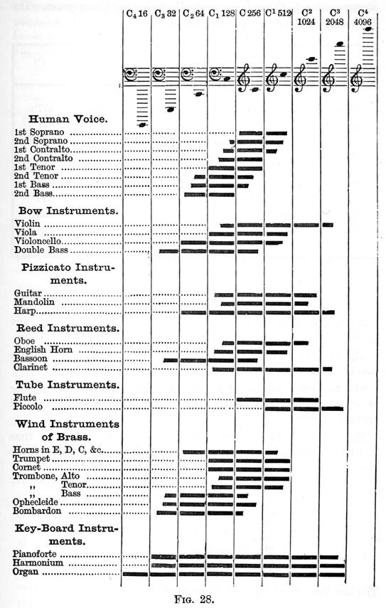
The lowest sound used in music, is found in the lowest note of the largest modern organs, and is produced by 16 1/2 vibrations per second; but so little of musical character does it possess, that it is never used except with its higher octaves. The musical character continues to be very imperfect for some distance above this limit; in fact, until we get to above twice this number of vibrations per second. The highest limit of musical pitch at the present time is about C4, a sound corresponding to about 4,000 vibrations per second. Very much higher sounds than this can be heard, but they are too shrill to be of any use in music. Fig. 28, which explains itself, shows the limits of pitch of the chief musical instruments.
The note C in the treble staff is the sound that musicians usually take as a basis of pitch; this, once fixed, all the other sounds of the musical scale are readily determined. But, unfortunately, at the present day, there are a very large number of vibration numbers, corresponding to this note; in other words, there is no universally recognised standard. It appears from Mr. Ellis's paper on "The History of Musical Pitch" that the vibration number corresponding to C has been gradually rising for many years. The following are a few of the chief standards.
| Standard | A | C1 | |
| Pythagorean | 432 | 512 | |
| Diapason Normal, 1859 | 435 | 517.3 | |
| Society of Arts, 1886 | - | 517.3 | |
| Tonic Sol-fa | - | 517.3 | |
| Pianofort Man' Assoc., 1891 | - | 517.3 | |
| Philharmonic, 1897 | 439 | 522 | |
| Before 1897 | - | 538 | |
| Kneller Hall, 1890 | - | 538 | |
| Crystal Palace | - | 538 | |
| Modern after 1940 | 440 | 523.24 | |
Summary.
A musical sound has three elements: Pitch, Intensity, and Quality.
The Pitch of a musical sound depends solely upon the vibration rate of the body that gives rise to it.
The Vibration Number of a given musical sound is the number of vibrations per second necessary to produce a sound of that particular pitch.
The principal instruments which have been used from time to time in determining the vibration numbers of musical sounds are:
Savart's Toothed Wheel. The Syren. The Sonometer or Monochord. Mayer's Graphic Method. The Cycloscope. The Tonometer.
The last three are by far the most accurate.
To ascertain the wavelength of any given sound - Divide the velocity of sound by its vibration number.
The wavelength of any given sound, increases with the temperature.
The temperature remaining constant, the length of the sound wave determines the pitch of the sound produced.
The range of musical pitch is from about 40 to 4,000 vibrations per second.